Thursday, December 29, 2011

Will my tractor be quality?

A college buddy of mine Michael Senkow, asked about my tractor. He said:
are the new tractors as good as professional ones? Part of why the expensive ones cost so much is their long term life right?....will these last as long?
Here is my answer:  I can make a tractor that is categorically better than a professional one.

That tractor is called LifeTrac. Here is my reasoning...

This is a four minute TED Talk in which the founder discusses his experiences with 'industrial quality'.


For me, this resonates. My experience of commercial products from our economy is almost universally dismal. I'm not surprised to hear an experienced farmer say that modern tractors are fragile.

What does my tractor have to be to be better? It has to have a long life with generally low maintenance costs. It must be versatile enough to do the jobs I need to do. It must be affordable to produce and safe enough to operate.

Long Life: LifeTrac is built with very heavy duty materials. Commercial ventures skimp on materials because consumers don't generally differentiate between a product that lasts 20 years and one that lasts 50 years. I've had too many tools break because of this kind of skimping.

Maintenance Costs: LifeTrac will be maintainable for a couple of reasons. It's very modular so one broken part can often be replaced on the spot with a spare. The tractor keeps working while the broken module goes to the shop. Each module is inexpensive too. I expect to repair or replace any module on my tractor for $500 or less. I probably couldn't get a professional tractor to the shop for that much.

Versatility: LifeTrac uses the Bobcat standard for bucket attachments. Additionally, it has auxiliary hydraulic power connections which can be used to attach arbitrary machines. The power module on the LifeTrac can be removed and replaced with a more powerful one. It will be able to do any job an equivalent commercial tractor can do.

Building Cost: I expect my LifeTrac to cost around $10,000 to build. That is about a quarter the price of a commercial tractor. Factor-e-Farm is already selling them for a profit. I don't know how many hours of labor it will take to build. I've already put a lot of time into the project and there is a long way to go. I'm tracking my time and money costs. I'll report on total costs when I'm done.

Safety: All heavy machinery is dangerous to operate. LifeTrac will be safe enough when operated carefully. It may be less safe than industry tractors-- I don't know enough about safety to judge.

The Long Run: Open Source projects improve and grow as they get more contributors. As more people build and use LifeTrac the failure modes, and inefficiencies will become apparent and the design will be improved. This will likely reduce cost, extend lifespan, add functionality, and improve safety.


Monday, December 19, 2011

2 Weeks, 1 Post. That's efficency.

My Christmas present to you is a post! I worked on Dec 8th and 15th. On the 8th I made my biggest mistake yet. You may recall that I had two flanges left to weld onto the hydraulic tank. On that faithful day, I welded both into place. Then I tried to screw in their hydraulic fittings. The top flange got a breather cap and the side flange got a male to male adapter:
Breather Cap on Left, Male to Male adaptor on right
That was the plan at least. The side flange went in just as planned. See it here:
The grey is the tank, the teal is weld and the green is the flange itself
The top flange went in like this:
Can you tell what's different? The flange is upside down. I could screw the breather cap in from the inside of the tank but it wouldn't fit from the outside. This was the state of affairs at the end of the 8th.


With a week to think about it, I decided I would skim the surface of the tank with a cutting tool and go back to square one. In the shop on the 15th I tried that and found that my cutting tool was too dull to cut through the weld (which was made of stainless steel). So I switched to old faithful: the boring head.

I would cut out the flange and weld on a new one. Half way through my first pass with the boring head I stopped. I had an idea! This was the situation:
What would you do? I decided to back off the cutting head and clean out the threads which were buggered a bit by the cut I'd just made. After that, the cap fit!


It probably saved me two weeks of recovery work. I hope you like my diagrams, they were fun to make. The whole process may seem clean by my description above. It was actually pretty messy. I got to practice clamping again-- here is my rig:

A really tall clamping arrangement

I finished my machining course, so I won't be working on the Power Cube until the spring semester. During the down time, I may write down my thoughts on why this is worth doing.

Time Card updated.

Sunday, December 4, 2011

Dec 1 - Cleaning and Welding the Reservoir

December 1st was another day with big plans. The reservoir tube was finally cut to spec. It was time to weld again. But first the tank needed to be cleaned out. Below you can see the specks of rust from the light rain that was falling when I carried it into the shop.


Mr. Lyons suggested that I clean off the inside with Scotch Bright. As I did, I noticed a lot of black dust coming off of the tube. It collected as a dusty shadow on the ground. I'm glad this stuff won't be running through my tractor.

Scotch Bright getting dirtier
Junk from the tube interior
To keep the interior from degrading I coated it with WD-40. This will prevent rust while I'm finishing the production.


Next I took the angle grinder to all the surfaces that I was going to weld (to take off the mill scale). Then I ground a chamfer into the flanges. This is a small angle that will allow fill material to flow between the surfaces that I will weld.

Ground and ready for welding
It turns out that professionals assemble gas tanks and other water tight things using TIG welding. TIG is a stick welding technology that gives extensive control over a weld. You apply heat and add material separately. This means that as you weld, you can backtrack and fill holes.

I decided to use TIG instead of MIG for this job. First I welded the large flange to the standoff tube. It went well except for a mild burn to my leg and a crater from my attempt to weld without any shielding gas.

The first section of the weld. The tip of the TIG gun is visible shown.
You can see that the chamfer leaves a gap between the flange and tube.
This is what happens when the shielding gas isn't turned on.
Fortunately you can weld back over the spot pretty easily.
I finished the flange and then welded the tube to the tank. I forgot to get a picture of that. I'll include that next week. I'm pretty happy with the product, the welds look good and are almost certainly air tight and very strong.

* Timesheet updated

Monday, November 28, 2011

Thoughts on Hydraulic Tank design for Power Cube

I know how I'm going to build my hydraulic tank. I've settled on a plan and I'm doing it. Still, the more I read, the more questions I have. The design I'll be building will work and be plenty sufficient, but perhaps it could be improved...

Painting the inside of the tank


It's not clear whether or not the inside of the tank should be painted. Some old hands say that it's not a concern. Others say that it is. I decided not to paint the inside of mine.

Mesh Filter on the Tank Intake


The design calls for a mesh strainer on the tank intake. This guy suggests that such strainers can be more harm than good. Most contaminants enter the system through hydraulic cylinders and pumps and such. It seems like those would be removed by the filter on the fluid return.

So it seems like the intake won't be removing much material. However, it will require the pump to pull harder to get a supply of fluid. This higher pressure lowers performance, and can cause cavitation (like in Hunt for the Red October). Finally, the tank is a fair bit more complex to build, because the current intake filter doesn't fit into the tank correctly.

Should this part be omitted entirely?

Baffling Design

Some hydraulic tanks are bisected my a baffle (info here). This baffle sits between the return and the intake. It's job is to force fluid travel the length of the tank. This causes it to mix and circulate before going back into the system. This helps with heat dissipation, lets sediment settle out, lets bubbles rise, and stops vortexes from forming between the surface of the fluid and the intake. Are these issues likely to manifest in the current design? Should a baffle be installed in the tank as protection?

Design for Maintenance

Some webpages suggest that hydraulic tanks have a drain plug on the bottom to make flushing out sediment easy. Should we put in one of these? Another suggestion is to have quick disconnects on the intake and return to make it easier to service the pump and such.

I think we can forego the disconnects because the tank is relatively small, and therefore easy to drain.

Design for Convenience

It might be helpful to have a window to see the level of the tank fluid. It might be helpful to have a thermometer to measure the operating temperature of the fluid. These seem like frills though-- how hard/expensive would they be to add?


Resources for Tank Design

General Tank Design - an advocate for painted interior, information on baffles

Some odds and ends for making tanks - Ever consider using a converted Keg (Aluminum, or Stainless Steel)?

Claim that Hydraulic intake filter can do harm.

Experienced Folk talking about practical tank design.

* Open & Closed questions updated

Saturday, November 19, 2011

Open and Closed Questions

As I wander through my process, I come up with questions. I'll record them here and record the answers once I find them.

Open Questions

Q: Would a baffle in the hydraulic reservoir improve performance?
Details here.

Q: Is NPT the right threading system for our connectors? This source suggests that UNO and BSPP are better for systems that will be disassembled and reassembled.

Closed Questions

Q: How will I attach the compressed air to the tank for my leak test?
A: Tom explains his answer here. It's a good one.


Q: Do I need to paint the inside of the hydraulic tank?
Details here.
A: No. Tom and others agree that it's a bad idea.


Q: Is the intake filter on the hydraulic reservoir harmful?
Details here.
A: No, the source that concerned me also explained that case drains shouldn't be filtered on return into the system, so have to be filtered on intake. See here.


Q: How should I clean the inside of the reservoir before welding it closed.
A: Scrub down with Scotch Bright and then wipe with Oil (I used WD-40) to protect it until the tank is in use.


Nov. 17 - Cutting the last hole.

This week I opened up my engine. Isn't it beautiful? (As a note, an engine laying on it's side will leak oil-- my poor car.)


I also drilled the last hole in the tank. It took about 2 hours. The challenge this time wasn't clamping, it was dealing with the height of the steel tube. It was a tight fit. In the picture below the Quill (the part that holds the cutting tool) is all the way up and I've only got an inch or so of clearance. 


When I was turning a spiral bit, I had to use a collet instead of a typical chuck. It worked though. Notice the clamping arrangement. The vice is holding a piece of angle iron to which the tube is clamped. I learned that you can move the plate on the jaw of the vice from one side to the other.


The angle iron wouldn't fit into the jaws in a 'normal' configuration, but this made the jaws have a much deeper throat. This way they could hold the angle. Finally a picture of your intrepid machinist:


* Timesheet updated.

Sunday, November 13, 2011

Production Steps for Hydraulic Reservoir

Here are the steps I plan to follow in making the hydraulic tank.
  1. Get all the materials.
    1. Steel Tube: 12" x 8" x 27.5" x 1/4". 
    2. Steel Plate: 12" x 8" x 1/4" (2x).
    3. Extension Tube: 2 1/2” Inner Diameter x 1/4" wall x 2" long
    4. 3 Flanges.
    5. Interior finish material.
  2. Drill holes in the Steel Tube.
  3. Grind all surfaces that will be welded.
  4. Weld on extension tube.
  5. Weld on flanges.
  6. Clean inside of tank and end plates.
  7. Weld on end plates.
  8. Leak Test.
  9. Fix any leaks (repeat 10 & 11 until leak test passes).
  10. *do the happy dance*
Notes:

The tank doesn't need to be painted on the inside (see why).

Friday, November 11, 2011

Progress for Nov 10

In my last post I mentioned my goals:
My goal for this week is to drill holes, weld on the ends of the tank, the flanges, and the extension tube.
 I was somewhat optimistic. This week I managed to cut two (out of three) holes in the square steel tubing. This may seem like a small achievement, but I'm quite proud of myself. Let me explain why.

When I wrote my goals, I was imagining a drill press with the right sized bit, quickly cutting the right sized holes. Turns out it's not quite that simple. Well, it could be that simple, but it wasn't for me. The devil, of course, is in the details. If I had the right sized bit, all I'd need to do is turn it with sufficient force and speed and the job is pretty much done!

Well, for holes two inches in diameter, that takes a pretty big motor. A motor that I didn't have. So I was going to have to bore out the hole. I didn't even know what boring out a hole was. Well, first thing you do is clamp the tubing to the mill table. Like so:


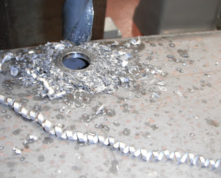
It's pretty nifty the kind of clamping you can do. There's a lot more complexity that I had expected. My first go, I didn't do a very good job and on the second cut, this end broke loose. I added the second clamp and thought I was done with clamping. I cut in initial hole with a spiral bit. It made a beautiful curlycue of waste.


That hole is an inch around. I needed to expand it to 1 and 7/16 inches in diameter. This is where boring comes in. It's a pretty cool process (though slow and-- you guessed it, boring). The bit has a single tooth and is held on an armature with an adjustable length.

Cutting tooth is sticking out the bottom, arm adjusts left and right
Each cut can expand the hole about 0.05 inches. So my expansion required about 8 passes... pretty slow. I learned how to use the auto feed on the quill of the mill (the part that moves up and down) which helped, but didn't make things faster. While making my cuts, I noticed some vibration in the tube, but nothing unacceptable.

The next hole was to be 2 and 3/8 inches in diameter. Much bigger. That's about 28 boring passes. As the hole got bigger, the cuts started to chatter and the surface being cut went from smooth to rippled. My instructor Mr. Lyons decided to help. He said simply "you got to hold it still". And we added a brace that clamped the top surface of the tube.


The problem was that the tube was so tall, the cutter was torquing the hole surface back and forth. Steel is pretty springy. There is a jack inside the tube pressing up, and a clamp above it pulling down. It was just amazing how much of a difference this made. Every cut thereafter was clean, and smooth. I could even make the cuts a little wider (.08 inches or so) which made the process faster.

The flanges sit securely in the holes as you can see:


Note that the large flange will stand a few inches off the surface of the tube to allow the strainer to fit.

My current open questions:

- How do I clean the inside of the cube? This will keep gunk out of the hydraulic fluid.
- Do I need to paint/finish the inside of the cube? I want to protect against rust.
- How will I attach the compressed air to the tank for my leak test?


Wednesday, November 9, 2011

Connecting Hydraulic Tank to Hydraulic Pump

After a few false starts and two weeks of missed work, I'm ready to go again. There are only a few components that go into a power cube. The one that I'll be working on this week is the Hydraulic Tank. Before beginning work on it, I took time to understand the component and its connections to the rest of the system.


The tank is shown to the right. When finished, it's almost exactly the width of the cube (28"). There are three holes. The top hole is for refilling the fluid. The hole on the top of the side is for return fluid. The bottom hole on the side is for drawing fluid. There is a strainer (shown) which is deeper than the square tube is deep. In order for it to fit, I'll add a short tube to the side.

Each of the holes will have a 'NPT Weld-In Tank Flange' attached to it. It took me a while to understand what that was. NPT is a threading standard, NPTF is female (innie) and NPTM is male (outie). So a weld-in tank flange is a piece of metal with a threaded hole that is meant to be welded to a piece of steel. You can see one here. With such a flange, I'll be able to screw useful hydraulic connections to the tank.

Exploded Hydraulic Connections
When making a tank like this you have to test for leaks. You do this by attaching an air hose to the tank and pressurizing it. Then cover the joints with soapy water and look for bubbles. Unfortunately, I don't know how to attach the air hose to the tank yet. Hmmmm.
Collapsed Hydraulic Connections

I talked to OSE Tom (who has been great) and he helped explain the hydraulic connections from the tank to the rest of the system. Armed with that knowledge, I ordered some things! They came in and I verified the fit. Left top shows an exploded view, Left bottom shows the parts collapsed as though they've been assembled.

My goal for this week is to drill holes, weld on the ends of the tank, the flanges, and the extension tube.


Note: Bill of Materials updated.

Thursday, October 27, 2011

My Suppliers

I've gotten parts and material from several different vendors. This is where I'm keeping track of them.

Lonsdale & Holtzman Sales Inc - A Hydraulic supplier in Baltimore.
Surplus Center - A web based parts supplier. Good website, enormous selection.
Small Engine Suppliers - Web based engine supplier. Very knowledgable staff. Helped me more with my questions on Briggs and Stratton engines than the Briggs and Stratton itself did.
Access Metals - A metal supplier in Baltimore. Helpful and knowledgeable staff.
Monumental Supply - Access Metals sent me here to order weld in flanges.

Tuesday, October 25, 2011

Progress for Oct 17 - 21

I was probably 6 times faster in the shop this week. I worked exclusively on the Power Cube frame. I welded the rest of the bottom square and all of the top square. The height of the steel frame may be changing so the uprights that I have are probably shorter than optimal. That means that turning these squares into a cube needs to be put off. For now I've decided to move from working on the frame to working on the hydraulic tank. This will give me time to think about the frame dimensions while still making progress.

I ordered the engine on Saturday, which I'm excited to get. I'll get some material locally this week. After that I'll be ordering the rest of the parts from Surplus Center. I started diagramming the hydraulic plumbing (draft on right) in an attempt to ensure I fully understand the tank. I'm pretty proud of my progress, but the diagram and my understanding are both quite incomplete. I contacted Tom, who has been helping me with various Power Cube related things. Hopefully he can help me shore up my understanding. I'm also hoping the diagram can become a useful part of the Power Cube documentation.

Sunday, October 23, 2011

On Engines

It's surprising how difficult it can be to get good data. I want to buy the right engine for my Power Cube. It turns out that there are a lot of engines out there. I was talking to a classmate about OSE and my project, and he pointed out that the parking lot we were in probably had over a hundred different engines in it. I am not qualified select an engine on my own.

I looked at the Bill of Materials for the Power Cube and was happy to see that the engine was already selected. It was a Brigs and Stratton 28 hp engine. Model Number 49M777. I didn't have to decide which engine to use. Well, the supplier that I'll be buying from offers three 'types' of the 49M777 engine. I asked my supplier and apparently the different 'types' are interchangeable. One type has a different governor spring, one type has a different spark plug. I suppose that the third type has nothing special.

So after much hemming and hawing, I've purchased an engine and await its delivery. Pretty amazing to be able to buy an internal combustion engine from somewhere in America and have it sent strait to my door.

A technical note: I spoke with a rep at Briggs and Stratton, the engine warrantee is invalidated by shortening the engine shaft.

Briggs and Stratton: has terrible phone help; has a poor website for comparing engines or getting engine specs.

Saturday, October 15, 2011

Progress for Oct 10 - 15

This is a really fun process. I get to take my time and do it right. This week I laid down the first weld on the Power Cube (version IV). I also started making progress on ordering my engine (post forthcoming).

I'm building the Frame of the Power Cube first. The frame is made of 1/4" thick angle iron. Its dimension are 27" long by 29" wide by 24" high. I will be making the cube taller so I don't have to shorten the shaft of the engine. The OSE folk turned me on to that modification. I'm waiting on them to get a new height. Until I know how tall to make the cube, I can only build the top and bottom squares of angle iron.


Welding Arrangement
The angle iron was already cut to length, so I could start immediately. My professor helped me set up the welder. I did a few practice welds to get the settings right, and get back into it-- I haven't welded in about 5 years. Getting the material into a proper square took some work, but I managed.

I laid down a few Tack welds to hold it all in place and remeasured for squareness. One of the sides had fallen out of alignment so I ground off the weld and fixed it. Now it was time to lay down some real welds.
Welded!

Tacked!

If you look at the picture labeled 'Tacked!', you'll notice a pretty big gap between the two edges. I'm not going to weld this joint until I add the piece of angle that gives the cube it's height. With a piece of angle blocking the gap it should be an easy weld.

It took quite a while to get set up and started, but I was finally rolling. The piece was tacked and square, and I was ready to weld! But it was time to clean up. I had a machining course to attend. So I have a half finished welding job to finish up next week.


Tuesday, October 11, 2011

Tracking Hours

Gary mentioned how it would be worth having a record of how many hours it took to complete my project. This was enough to spur me on to add it to my spreadsheet. Most of the time I spend won't actually be on the spreadsheet. I'm not going to record, research time, documentation time, or correspondence time. I also won't include time that I pay someone else to spend (many of my steel cuts are done by my supplier for example). What will be included is fabrication time. I'm a relatively untrained fabricator. This means I'm less efficient than many who would undertake this project. Still, for someone who has done some carpentry, a little welding and a lot of experimentation this may be a reasonable estimate.

In the end I think it will be of major value to the OSE project to have records like those that I'm collecting. To have lots of data points on the costs (material, time, energy) of a Power Cube would really strengthen the case for OSE based businesses. I'm happy to collect data for my little project and hope to see data for other projects. Another person tracking their costs would help me understand when my costs are reasonable and when I'm slow or my materials are expensive. This may help me (or others) save major money/time.

Anyone can ask for access to my records in case they want to look more closely, or in case they want to use them as a template for tracking their own costs.

Tuesday, September 27, 2011

Tracking the Materials and Cost of a Power Cube

Just a Power Cube requires a lot of components. I'm worried that the design of the Cube will change, so I'm buying parts piecemeal. I'm also curious how much a Power Cube costs. I made a spreadsheet to track what I've ordered and how much it costs. From this I'll be able to compute total cost. You can see my spreadsheet here (and below). I copied liberally from the spreadsheets that OSE provides for the Cube. I will update it as work proceeds.


Helpful Resources

This is just a list of URLs to help me find things quickly.

Tom's Dallas Log
My Log
BOM

Saturday, September 24, 2011

Progress for Sept 19 - 23

My first posts will be a little backward because there's a lot to say and I want to try and be organized about saying it. So I'll start with the most concrete stuff. This week I started building a Power Cube which will be the power source for many machines to come.

On Monday I ordered 20 feet of Angle Iron from Access Metals (the Total cost for this was 68.90$). This would be the frame of the Power Cube. Sandy drove to the shop and picked it up. To fit in the Neon, it was cut into 2 six foot pieces and 1 seven foot piece.

On Thursday I left work early for my machining course at CCBC. I had about 1.5 hours to work before class started. I managed to cut all the long pieces of steel in that time.
The first cut on my tractor!
At the end of the work, I realized that the instructions had left out some additional cuts. I would need more steel. I conferred with Tom and he confirmed a change to the instructions. I would need a total of 408 inches of angle iron. That's another 168".

We'll get that before next Thursday.