Monday, November 28, 2011

Thoughts on Hydraulic Tank design for Power Cube

I know how I'm going to build my hydraulic tank. I've settled on a plan and I'm doing it. Still, the more I read, the more questions I have. The design I'll be building will work and be plenty sufficient, but perhaps it could be improved...

Painting the inside of the tank


It's not clear whether or not the inside of the tank should be painted. Some old hands say that it's not a concern. Others say that it is. I decided not to paint the inside of mine.

Mesh Filter on the Tank Intake


The design calls for a mesh strainer on the tank intake. This guy suggests that such strainers can be more harm than good. Most contaminants enter the system through hydraulic cylinders and pumps and such. It seems like those would be removed by the filter on the fluid return.

So it seems like the intake won't be removing much material. However, it will require the pump to pull harder to get a supply of fluid. This higher pressure lowers performance, and can cause cavitation (like in Hunt for the Red October). Finally, the tank is a fair bit more complex to build, because the current intake filter doesn't fit into the tank correctly.

Should this part be omitted entirely?

Baffling Design

Some hydraulic tanks are bisected my a baffle (info here). This baffle sits between the return and the intake. It's job is to force fluid travel the length of the tank. This causes it to mix and circulate before going back into the system. This helps with heat dissipation, lets sediment settle out, lets bubbles rise, and stops vortexes from forming between the surface of the fluid and the intake. Are these issues likely to manifest in the current design? Should a baffle be installed in the tank as protection?

Design for Maintenance

Some webpages suggest that hydraulic tanks have a drain plug on the bottom to make flushing out sediment easy. Should we put in one of these? Another suggestion is to have quick disconnects on the intake and return to make it easier to service the pump and such.

I think we can forego the disconnects because the tank is relatively small, and therefore easy to drain.

Design for Convenience

It might be helpful to have a window to see the level of the tank fluid. It might be helpful to have a thermometer to measure the operating temperature of the fluid. These seem like frills though-- how hard/expensive would they be to add?


Resources for Tank Design

General Tank Design - an advocate for painted interior, information on baffles

Some odds and ends for making tanks - Ever consider using a converted Keg (Aluminum, or Stainless Steel)?

Claim that Hydraulic intake filter can do harm.

Experienced Folk talking about practical tank design.

* Open & Closed questions updated

Saturday, November 19, 2011

Open and Closed Questions

As I wander through my process, I come up with questions. I'll record them here and record the answers once I find them.

Open Questions

Q: Would a baffle in the hydraulic reservoir improve performance?
Details here.

Q: Is NPT the right threading system for our connectors? This source suggests that UNO and BSPP are better for systems that will be disassembled and reassembled.

Closed Questions

Q: How will I attach the compressed air to the tank for my leak test?
A: Tom explains his answer here. It's a good one.


Q: Do I need to paint the inside of the hydraulic tank?
Details here.
A: No. Tom and others agree that it's a bad idea.


Q: Is the intake filter on the hydraulic reservoir harmful?
Details here.
A: No, the source that concerned me also explained that case drains shouldn't be filtered on return into the system, so have to be filtered on intake. See here.


Q: How should I clean the inside of the reservoir before welding it closed.
A: Scrub down with Scotch Bright and then wipe with Oil (I used WD-40) to protect it until the tank is in use.


Nov. 17 - Cutting the last hole.

This week I opened up my engine. Isn't it beautiful? (As a note, an engine laying on it's side will leak oil-- my poor car.)


I also drilled the last hole in the tank. It took about 2 hours. The challenge this time wasn't clamping, it was dealing with the height of the steel tube. It was a tight fit. In the picture below the Quill (the part that holds the cutting tool) is all the way up and I've only got an inch or so of clearance. 


When I was turning a spiral bit, I had to use a collet instead of a typical chuck. It worked though. Notice the clamping arrangement. The vice is holding a piece of angle iron to which the tube is clamped. I learned that you can move the plate on the jaw of the vice from one side to the other.


The angle iron wouldn't fit into the jaws in a 'normal' configuration, but this made the jaws have a much deeper throat. This way they could hold the angle. Finally a picture of your intrepid machinist:


* Timesheet updated.

Sunday, November 13, 2011

Production Steps for Hydraulic Reservoir

Here are the steps I plan to follow in making the hydraulic tank.
  1. Get all the materials.
    1. Steel Tube: 12" x 8" x 27.5" x 1/4". 
    2. Steel Plate: 12" x 8" x 1/4" (2x).
    3. Extension Tube: 2 1/2” Inner Diameter x 1/4" wall x 2" long
    4. 3 Flanges.
    5. Interior finish material.
  2. Drill holes in the Steel Tube.
  3. Grind all surfaces that will be welded.
  4. Weld on extension tube.
  5. Weld on flanges.
  6. Clean inside of tank and end plates.
  7. Weld on end plates.
  8. Leak Test.
  9. Fix any leaks (repeat 10 & 11 until leak test passes).
  10. *do the happy dance*
Notes:

The tank doesn't need to be painted on the inside (see why).

Friday, November 11, 2011

Progress for Nov 10

In my last post I mentioned my goals:
My goal for this week is to drill holes, weld on the ends of the tank, the flanges, and the extension tube.
 I was somewhat optimistic. This week I managed to cut two (out of three) holes in the square steel tubing. This may seem like a small achievement, but I'm quite proud of myself. Let me explain why.

When I wrote my goals, I was imagining a drill press with the right sized bit, quickly cutting the right sized holes. Turns out it's not quite that simple. Well, it could be that simple, but it wasn't for me. The devil, of course, is in the details. If I had the right sized bit, all I'd need to do is turn it with sufficient force and speed and the job is pretty much done!

Well, for holes two inches in diameter, that takes a pretty big motor. A motor that I didn't have. So I was going to have to bore out the hole. I didn't even know what boring out a hole was. Well, first thing you do is clamp the tubing to the mill table. Like so:


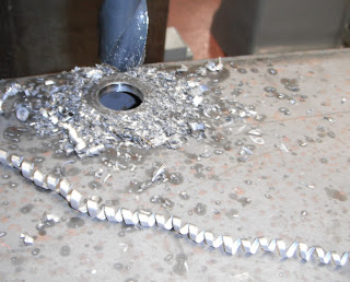
It's pretty nifty the kind of clamping you can do. There's a lot more complexity that I had expected. My first go, I didn't do a very good job and on the second cut, this end broke loose. I added the second clamp and thought I was done with clamping. I cut in initial hole with a spiral bit. It made a beautiful curlycue of waste.


That hole is an inch around. I needed to expand it to 1 and 7/16 inches in diameter. This is where boring comes in. It's a pretty cool process (though slow and-- you guessed it, boring). The bit has a single tooth and is held on an armature with an adjustable length.

Cutting tooth is sticking out the bottom, arm adjusts left and right
Each cut can expand the hole about 0.05 inches. So my expansion required about 8 passes... pretty slow. I learned how to use the auto feed on the quill of the mill (the part that moves up and down) which helped, but didn't make things faster. While making my cuts, I noticed some vibration in the tube, but nothing unacceptable.

The next hole was to be 2 and 3/8 inches in diameter. Much bigger. That's about 28 boring passes. As the hole got bigger, the cuts started to chatter and the surface being cut went from smooth to rippled. My instructor Mr. Lyons decided to help. He said simply "you got to hold it still". And we added a brace that clamped the top surface of the tube.


The problem was that the tube was so tall, the cutter was torquing the hole surface back and forth. Steel is pretty springy. There is a jack inside the tube pressing up, and a clamp above it pulling down. It was just amazing how much of a difference this made. Every cut thereafter was clean, and smooth. I could even make the cuts a little wider (.08 inches or so) which made the process faster.

The flanges sit securely in the holes as you can see:


Note that the large flange will stand a few inches off the surface of the tube to allow the strainer to fit.

My current open questions:

- How do I clean the inside of the cube? This will keep gunk out of the hydraulic fluid.
- Do I need to paint/finish the inside of the cube? I want to protect against rust.
- How will I attach the compressed air to the tank for my leak test?


Wednesday, November 9, 2011

Connecting Hydraulic Tank to Hydraulic Pump

After a few false starts and two weeks of missed work, I'm ready to go again. There are only a few components that go into a power cube. The one that I'll be working on this week is the Hydraulic Tank. Before beginning work on it, I took time to understand the component and its connections to the rest of the system.


The tank is shown to the right. When finished, it's almost exactly the width of the cube (28"). There are three holes. The top hole is for refilling the fluid. The hole on the top of the side is for return fluid. The bottom hole on the side is for drawing fluid. There is a strainer (shown) which is deeper than the square tube is deep. In order for it to fit, I'll add a short tube to the side.

Each of the holes will have a 'NPT Weld-In Tank Flange' attached to it. It took me a while to understand what that was. NPT is a threading standard, NPTF is female (innie) and NPTM is male (outie). So a weld-in tank flange is a piece of metal with a threaded hole that is meant to be welded to a piece of steel. You can see one here. With such a flange, I'll be able to screw useful hydraulic connections to the tank.

Exploded Hydraulic Connections
When making a tank like this you have to test for leaks. You do this by attaching an air hose to the tank and pressurizing it. Then cover the joints with soapy water and look for bubbles. Unfortunately, I don't know how to attach the air hose to the tank yet. Hmmmm.
Collapsed Hydraulic Connections

I talked to OSE Tom (who has been great) and he helped explain the hydraulic connections from the tank to the rest of the system. Armed with that knowledge, I ordered some things! They came in and I verified the fit. Left top shows an exploded view, Left bottom shows the parts collapsed as though they've been assembled.

My goal for this week is to drill holes, weld on the ends of the tank, the flanges, and the extension tube.


Note: Bill of Materials updated.